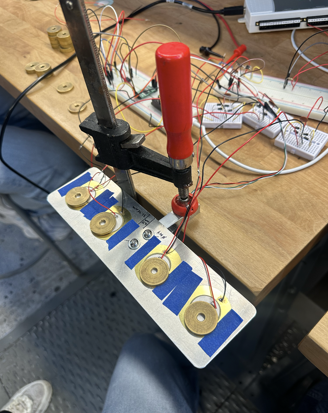
Energy Harvesting with Piezoelectric Transducers
UC Berkeley ME103: Experimentations and Measurements
We can charge an electric car with the sun, but can we charge our phones by simply walking? This study aims to explore piezoelectric materials and investigate the feasibility of energy harvesting piezoelectric transducers while under the mechanical stress of a footstep
What is piezoelectricity?
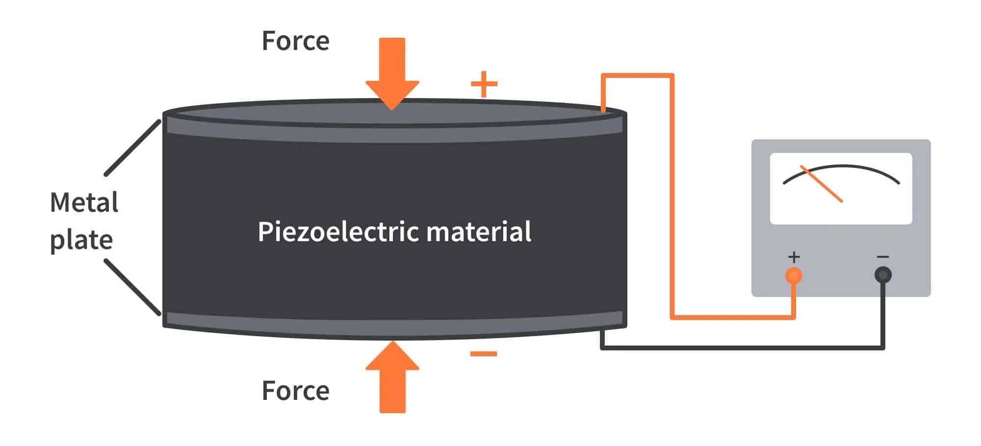
…and how can we use it?
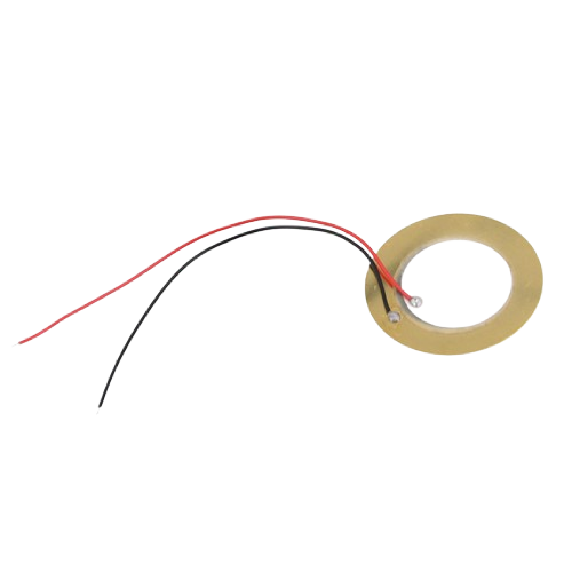
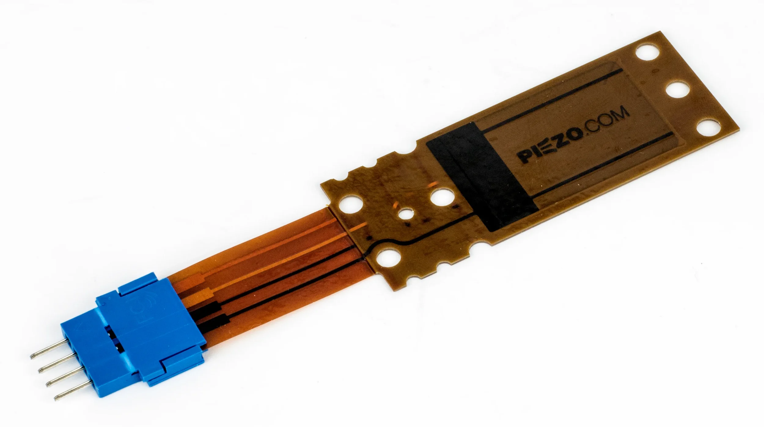
Piezoelectric transducers are devices that convert mechanical stress into electrical voltage using the piezoelectric effect. These transducers are available in various forms, such as thin films, bulk ceramics, and flexible sheets, allowing them to be tailored for specific applications.
Piezoelectric materials are promising for energy harvesting applications, converting mechanical energy into electrical energy due to the innate misalignment of its crystal lattice structure, with potential use in wearable and structural systems.
Read our scientific report here!
Project Phases

Stage 1: Methods
Stage 2: Circuitry
Stage 3: Data Collection
Final Report
Stage 1: Methods
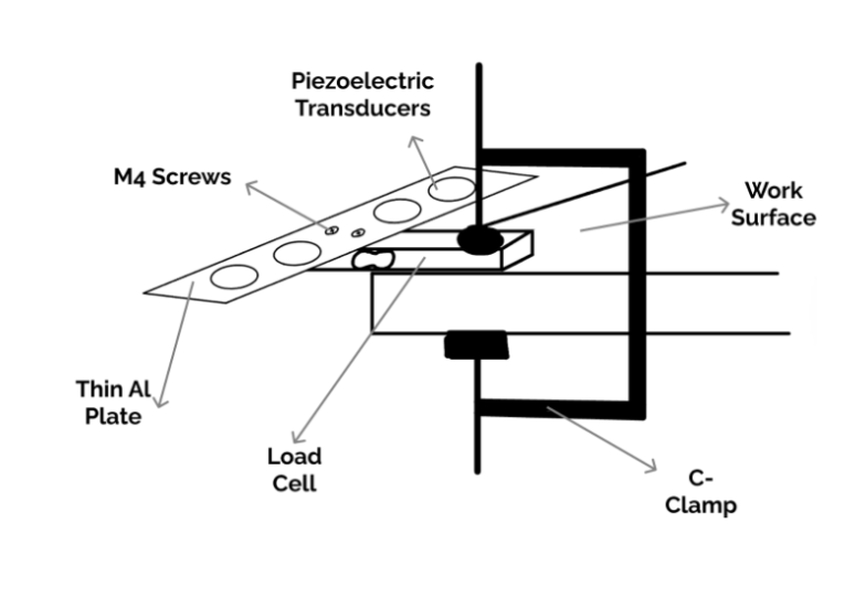
Goal 1: Equally disperse piezoelectric transducers for holistic foot mapping at toes, ball of foot, heel of foot, and back of foot
Stage 2: Circuitry
Transducers:
Full Wave Rectifier Circuit
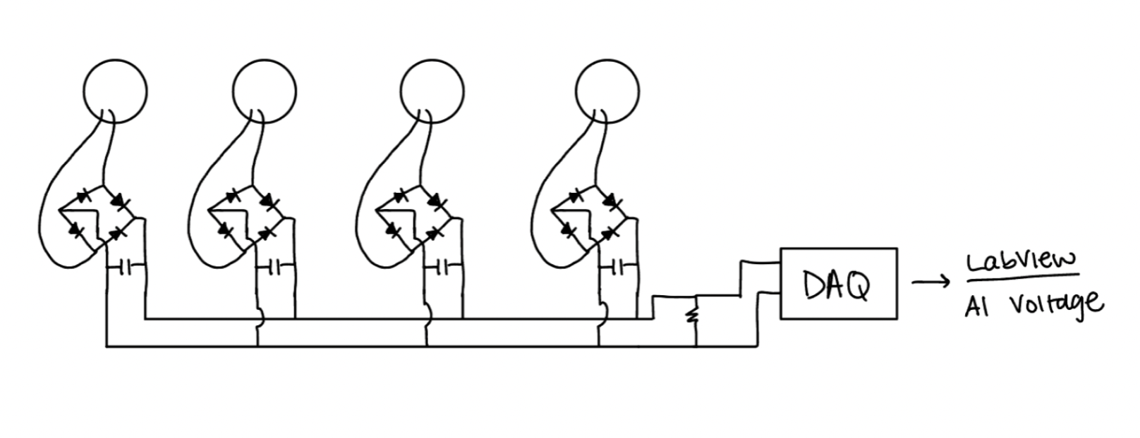
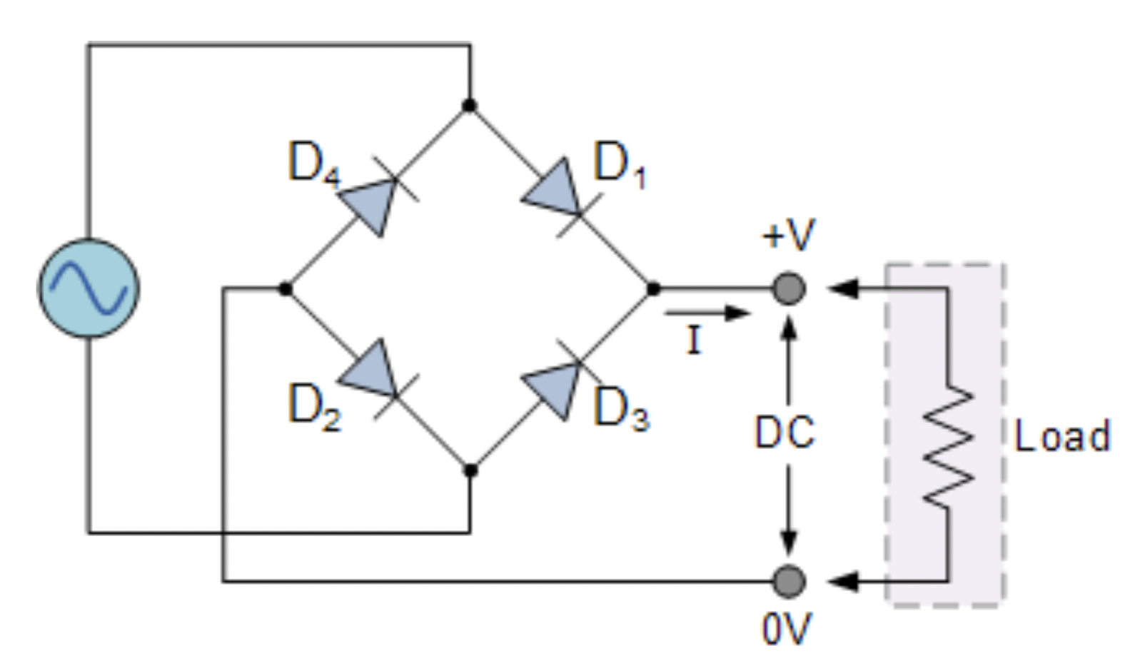
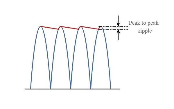
We used a full-wave rectifier to steady the half-wave AC spikes into a constant DC output. We made this full-wave rectifier by placing 4 zener diodes in a bridge formation.
Transducers:
Smoothing Capacitor
We connected a smoothing capacitor to the output of each full-wave rectifying circuit. The energy stored helps maintain the output voltage for measurement and when powering any device when the input signal from the transducers fluctuate or drop due to minimal mechanical stress. This ensures smooth power delivery.
1
Stage 3: Data Collection
1. Reading
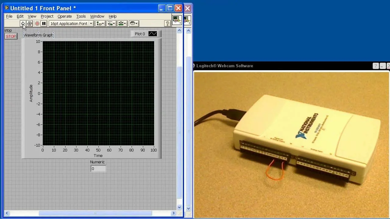
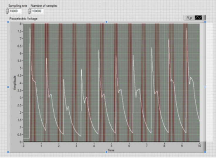
These voltage data points were collected over 10 second intervals with 100,000 samples being taken at a rate of 10000 Hz. These were then combined with the internal resistance of the circuit configuration to derive power dissipated overtime.
2. Formula
Current = Voltage / Resistance (R=1Mohm)
Power = Current*Voltage
1. Calibration
Known Weight * Calibration Factor = Reading
We placed multiple weights, each of a known 12.8g value, to calibrate until the known weight matched the readings, with a final calibration factor of -1020
2. Formula
Force (N) =(scale.get_units()*.001) kg*9.81 m/s2
Stage 4: Findings
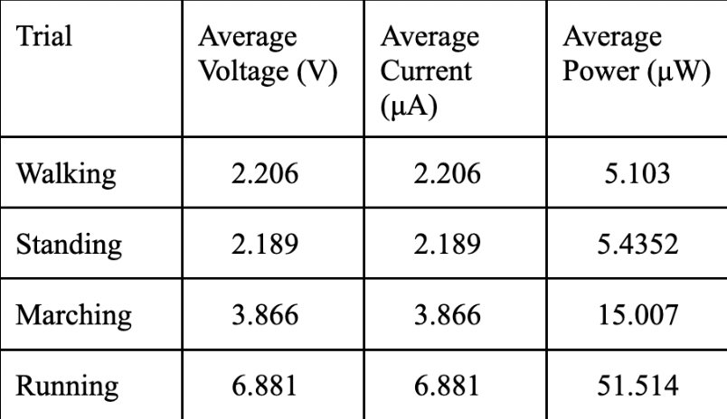
@ Minimum Requirements: 5V, .5A, 2.5WGoing for a run could reach the minimum voltage requirements for a USB charge, yet piezoelectric transducers fall short in available current, making the power inadequate.
2
Standing
For the future
Properly package the testing plate into a shoe to allow for full force and pace.
3
Goal shifting: Match thin sheet transducers with low-Watt items of its size, such as sensors, activity monitors, energy storage.
Conduct further studies on foat-load mapping to analyze where to concentrate more transducers
Goal 2: Collect load cell data using fixed-end beam calculation
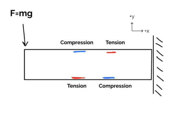
Load Cell:
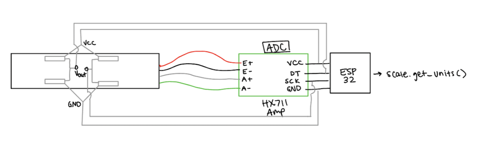
HX711 Amplifier
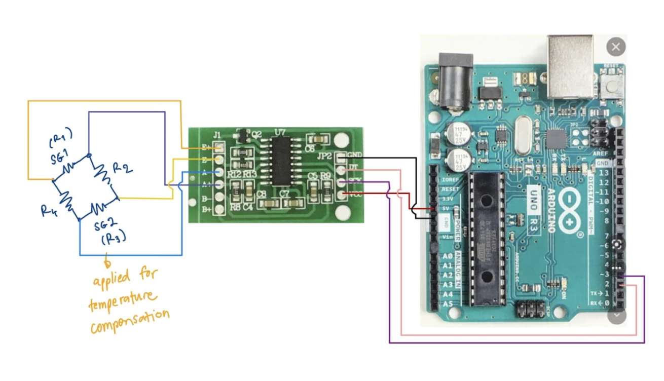
Our load cell’s 4 wires are connected to the HX711 Amplifier, which is fed directly into our ESP32 Microcontroller. We are able to write code on the Arduino program using the amplifier library to calibrate and read the load cell values.
Load Cell:
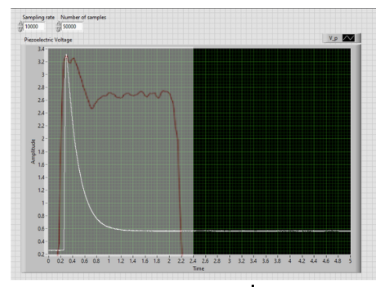
Red line: Load CellBlack line: Piezo transducer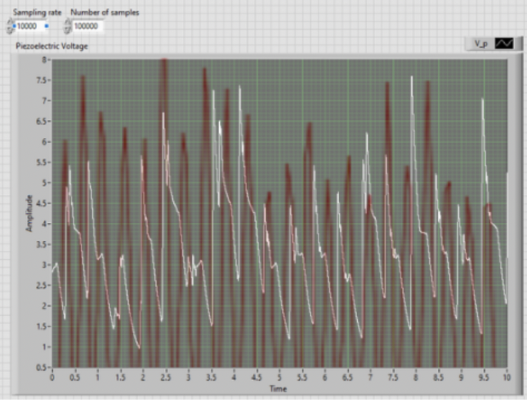
Marching
Running